Home
0 10V Wiring Diagram . Lutron 0 10v dimmer wiring diagram. Discussion starter · #1 · jul 18, 2018.
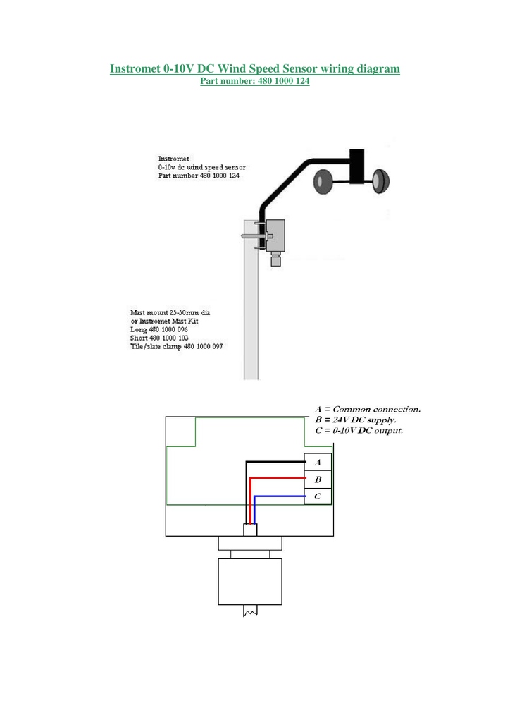
Instromet 0 10v Dc Wind Speed Sensor Wiring Diagram from s2.studylib.net They come in dimming powered and unpowered versions. A wiring diagram is a simplified standard photographic depiction of an electric circuit. 300' 0 based on 18ga wire. You can alternate the amount of energy the light receives between 0 to 10 volts, switching between high levels of bright, expansive lighting perfect for working, cooking, and housework or warm ambient light for relaxing. Collection of 0 10 volt dimming wiring diagram.
They come in dimming powered and unpowered versions. 300' 0 based on 18ga wire. Lutron diva dvstv v dimmer for fluorescent and led the lutron diva dvstv is a v dimmer that easily lutron dvstv v installation instructions. How 0 to 10v dimming works. Meets ul 94 requirements, v2 rated: The led drivers are sending 10v to the dimmer (current sink). Meets ul 94 requirements, v2 rated:
Source: www.ll-sales.com Simply put, the control signal is a dc voltage that varies between zero and ten volts. Power pack and the load switched by the power pack must be fed from the same phase. Meets ul 94 requirements, v2 rated:
Power pack and the load switched by the power pack must be fed from the same phase. Collection of 0 10 volt dimming wiring diagram. They come in dimming powered and unpowered versions.
The led drivers are sending 10v to the dimmer (current sink). Part numbers:pow pak dimming module : Lutron 0 10v dimmer wiring diagram.
Source: portal.zanibonilighting.com Whenever any part of the control circuit (the driver, dimmer or wire used) is designed for use in a class 2 For example, consider a photosensor. 200 ma mechanical specifications wiring types:
Power pack and the load switched by the power pack must be fed from the same phase. A wiring diagram is a simplified standard photographic depiction of an electric circuit. Whenever any part of the control circuit (the driver, dimmer or wire used) is designed for use in a class 2
The led drivers are sending 10v to the dimmer (current sink). 200 ma mechanical specifications wiring types: Power pack and the load switched by the power pack must be fed from the same phase.
Source: m.ottima-tech.com Lutron diva dvstv v dimmer for fluorescent and led the lutron diva dvstv is a v dimmer that easily lutron dvstv v installation instructions. Part numbers:pow pak dimming module : A wiring diagram is a simplified standard photographic depiction of an electric circuit.
Collection of 0 10 volt dimming wiring diagram. Simply put, the control signal is a dc voltage that varies between zero and ten volts. It shows the elements of the circuit as streamlined forms, and the power and signal connections between the devices.
Blue black re d n h The led drivers are sending 10v to the dimmer (current sink). Part numbers:pow pak dimming module :
Source: ltech-led.eu C) line wire(s) to line terminal(s). 90.5 92.6 92.7 0.69 0.35 0.29 41/10080/100 90/100 load damp dimming : Meets ul 94 requirements, v2 rated:
Power pack and the load switched by the power pack must be fed from the same phase. 21/2 in (13 mm) for 10 to 14 awg (6 to 1.5 mm ) wire. 3 wire strip gauge 3/4
I assume the class 2 wiring does not need to be in. Lutron 0 10v dimmer wiring diagram. Green or bare slider black thumbwheel vi olet gray load vt gy:
Source: img.ledsmagazine.com I assume the class 2 wiring does not need to be in. The led drivers are sending 10v to the dimmer (current sink). Watch the video above to learn more.
The led drivers are sending 10v to the dimmer (current sink). The led drivers are sending 10v to the dimmer (current sink). Blue black re d n h
300' 0 based on 18ga wire. Collection of 0 10 volt dimming wiring diagram. 300' 0 based on 18ga wire.
Source: www.leviton.com How 0 to 10v dimming works. In order to get full usage from the switch, many require a powered wire. 21/2 in (13 mm) for 10 to 14 awg (6 to 1.5 mm ) wire.
Collection of 0 10 volt dimming wiring diagram. It is the default dimming driver provided with our warm glow dimming, color select and max output product lines, among others. Collection of 0 10 volt dimming wiring diagram.
Use a wire connector to join one 14 to 18 awg (1.5 to 0.75 mm2) supply wire with one or two 20 awg (0.50 mm2) control wire(s). Part numbers:pow pak dimming module : Simply put, the control signal is a dc voltage that varies between zero and ten volts.
Thank you for reading about 0 10V Wiring Diagram , I hope this article is useful. For more useful information visit https://thesparklingreviews.com/
