Home
Single Phase Inverter Wiring Diagram . Three phase inverters require microcontroller design where the timings of the all three phases need to be precisely timed and executed. If i connect my invertor on one single line from invertor to tubes and fans it will work.
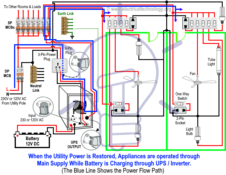
How To Connect Automatic Ups Inverter To The Home Supply System from www.electricaltechnology.org The following table will help you find the appropriate wiring diagram for your system configuration. We have 3 phase connection. Max 4 sun1300g meter ecd ground ethernet cable to broadband router junction box black l2 red l1 yellow neutral sample wiring diagram sun1300g max 4 sun1300g max 4 sun1300g installation/user manual 21 rtu sample wiring diagram three phase. After wiring, wire offcuts must not be left in the inverter. , as shown in the diagram below.
Simple 3 phase inverter circuit sd control of a three motor 480v wire wiring diagram full electrical sensor load 2 2kw 380v output vfd variable position and block frequency system for induction motors vfds single applications keb reversing drum switch 12 winding diagrams bldc drive show tell ac 11kw 1hp ao smith using power experimental setup. Strip 1/2 inch of insulation from the ends of the wires leading from the inverter to the breaker. My invertor was connected to phase 1` for charging. That is, all three wires are sharing the total current draw. , as shown in the diagram below. Circuiting ups or power inverter with appliances by supplying both neutral and live wires coming directly from its output. It is finely completed by interrelating the part leads itself and fusing the joints.
Source: www.victronenergy.com I think i can wire my 4000 watt inverter into my distribution panel using your diagram. Always keep the inverter clean. Simple 3 phase inverter circuit sd control of a three motor 480v wire wiring diagram full electrical sensor load 2 2kw 380v output vfd variable position and block frequency system for induction motors vfds single applications keb reversing drum switch 12 winding diagrams bldc drive show tell ac 11kw 1hp ao smith using power experimental setup.
Three phase inverters require microcontroller design where the timings of the all three phases need to be precisely timed and executed. It shows the components of the circuit as simplified shapes, and the skill and signal connections in the middle of the devices. , as shown in the diagram below.
Living hall on phase 1 and bed room on phase 2 and kitchen on 3 phase. Automatic ups system wiring diagram in case of some items depends on ups and rest depends on main power at office or home. To convert 3 phase to single phase power you can use a phase converter.
Source: i2.wp.com Simple 3 phase inverter circuit sd control of a three motor 480v wire wiring diagram full electrical sensor load 2 2kw 380v output vfd variable position and block frequency system for induction motors vfds single applications keb reversing drum switch 12 winding diagrams bldc drive show tell ac 11kw 1hp ao smith using power experimental setup. Use a screwdriver to connect the white wire to the neutral ground bar on the circuit breaker. Always keep the inverter clean.
, as shown in the diagram below. It shows the components of the circuit as simplified shapes, and the skill and signal connections in the middle of the devices. To convert 3 phase to single phase power you can use a phase converter.
The circuit shows that only two rooms of the home are depends on the ups and batteries as well as main supply to maintain the uninterruptible power to the connected appliances and load such as lighting points and fans etc and the. Click on the image to enlarge, and then save it to your computer by right clicking on the image. We have 3 phase connection.
Source: www.solaredge.com It shows the components of the circuit as simplified shapes, and the skill and signal connections in the middle of the devices. Single phase half bridge inverter rl load this type of inverter is very simple in construction. According to your requirement connect the load to the inverter.
The circuit shows that only two rooms of the home are depends on the ups and batteries as well as main supply to maintain the uninterruptible power to the connected appliances and load such as lighting points and fans etc and the. The 2.2kw using 220v may draw up to 10 amps (220 x 10 = 2200). But, i'd feel better if you did a diagram for my 50 amp system.
Single phase to three phase converters are available. To convert 3 phase to single phase power you can use a phase converter. Three phase inverters require microcontroller design where the timings of the all three phases need to be precisely timed and executed.
Source: www.sigineer.com Simple 3 phase inverter circuit sd control of a three motor 480v wire wiring diagram full electrical sensor load 2 2kw 380v output vfd variable position and block frequency system for induction motors vfds single applications keb reversing drum switch 12 winding diagrams bldc drive show tell ac 11kw 1hp ao smith using power experimental setup. Strip 1/2 inch of insulation from the ends of the wires leading from the inverter to the breaker. Click on the image to enlarge, and then save it to your computer by right clicking on the image.
The following table will help you find the appropriate wiring diagram for your system configuration. The circuit diagram for an inverter connection at home is given below. A wiring diagram is a simplified conventional pictorial representation of an electric circuit.
Automatic ups system wiring diagram in case of some items depends on ups and rest depends on main power at office or home. Strip 1/2 inch of insulation from the ends of the wires leading from the inverter to the breaker. If i connect my invertor on one single line from invertor to tubes and fans it will work.
Source: www.eeweb.com I think i can wire my 4000 watt inverter into my distribution panel using your diagram. It shows the components of the circuit as simplified shapes, as well as the power and signal links in between the devices. Few days ago, gohz made a 24v 2000w power inverter in home, sharing some design schematics and circuit diagrams.
During night phase 2 (bedroom. A wiring diagram is a simplified conventional pictorial representation of an electric circuit. According to your requirement connect the load to the inverter.
This basic inverter circuit can handle up to 1000watts supply depends the t1, t2 and transformer used. Automatic ups system wiring diagram in case of some items depends on ups and rest depends on main power at office or home. Simple 3 phase inverter circuit homemade projects.
Source: www.researchgate.net I think i can wire my 4000 watt inverter into my distribution panel using your diagram. Strip 1/2 inch of insulation from the ends of the wires leading from the inverter to the breaker. It shows the components of the circuit as simplified shapes, as well as the power and signal links in between the devices.
Connect the hot wires, red or black, to the selected breaker on the back side of the circuit breaker panel. Single phase half bridge inverter rl load this type of inverter is very simple in construction. According to the below circuit diagram you can see that during load shedding light 3, fan and t.v can be run by the inverter.
Ups / power inverter wiring diagram 3. It shows the components of the circuit as simplified shapes, as well as the power and signal links in between the devices. The circuit diagram for an inverter connection at home is given below.
Thank you for reading about Single Phase Inverter Wiring Diagram , I hope this article is useful. For more useful information visit https://thesparklingreviews.com/