Home
Cold Room Control Panel Wiring Diagram . They look like the rungs in a ladder hence the name ladder schematic. Cold room ambient temperature range is 5 c to 40 c.
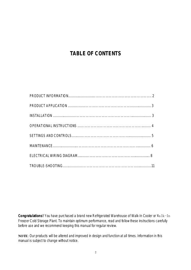
Walk In Cooler Freezer Cold Room Plant Refrigerated Cold Storage from image.slidesharecdn.com • having completed the wiring, please check with the wiring diagram to ensure it has been done correctly. Primary led (14 segment amber colour) secondary led (7 segment green colour) 10 status icons. Blodgett ef 111 wiring diagram sample. A wiring diagram is a streamlined traditional photographic representation of an electrical circuit. Cold room control panel wiring diagram sample.
Electrical wiring diagram for bedroom machine units unit coolers starting wires and wire threading pipes that are used in room lighting. The main devices that normally need to be managed by an electronic controller are: It shows the elements of the circuit as simplified shapes, and also the power as well as signal connections in between the devices. Advanced multifunction controllers with temperature and humidity management. • having completed the wiring, please check with the wiring diagram to ensure it has been done correctly. A wiring diagram shows as closely as possible the actual location of all component parts of the device. It allows the user to control all the components on a refrigeration system:
Source: i1.wp.com 4 digit, 1 dot matrix display to display all parameters. If an alarm is tripped, the display will show one warns the operator by displaying alarm codes and of the following messages:. 0420 cold room wiring diagram pdf.
Electrical wiring cold room control panel wiring diagram involve some pictures that related one another. The main devices that normally need to be managed by an electronic controller are: Water flowing pipes melting frost preserving cold electric warm wires and heat preservations in the melting water flowing pipe.
A wiring diagram generally provides info. Hp/lp , aux faults for compressor protection. Probes for measuring room and defrost temperature (if featured) compressor
Source: lh3.googleusercontent.com Room air cooler wiring diagram # 2. Blodgett ef 111 wiring diagram sample. Cold room ambient temperature range is 5 c to 40 c.
For more videos dont forget to subscribe. Thermostat and other control units of the cold storage room are properly set. The main devices that normally need to be managed by an electronic controller are:
Touch keypad with 8 keys. In this video how compressor is controlled is shown.next video will be on how control wiring is done.1)wireless refrigeration digital manifold gauge set hva. Electrical wiring cold room control panel wiring diagram involve some pictures that related one another.
Source: 3.bp.blogspot.com Introduction ultracella is a family of products consisting of a control system for the the accessory modules allow: General components of cold rooms: Control panel freezer room cold roomsupply & service cold room , ripening chamber & blast freezerscp coldshop no:
If an alarm is tripped, the display will show one warns the operator by displaying alarm codes and of the following messages:. Primary led (14 segment amber colour) secondary led (7 segment green colour) 10 status icons. A wiring diagram is a streamlined traditional pictorial representation of an electric circuit.
Mount control panel with adequate clearance from excessive heat sources such as appliances to prevent damage of the components. It shows the elements of the circuit as simplified shapes, and also the power as well as signal connections in between the devices. For more videos dont forget to subscribe.
Source: sc01.alicdn.com Blodgett ef 111 wiring diagram sample. A wiring diagram is a streamlined traditional pictorial representation of an electrical circuit. They look like the rungs in a ladder hence the name ladder schematic.
Cold room control panel wiring diagram sample. Typically, cold rooms with onboard condensers or packaged units are used in small stores, while cold rooms served by compressor racks are used in supermarkets and distribution centers. Front access to the automatic fuse and motor protector for the compressor and an innovative design combine to make it the ideal choice for effective refrigeration control.
Cold room control panel wiring diagram sample variety of cold room control panel wiring diagram. Connect sensor wires to the terminals labeled room. 4 digit, 1 dot matrix display to display all parameters.
Source: i.ytimg.com Room air cooler wiring diagram # 2. Electrical wiring cold room control panel wiring diagram involve some pictures that related one another. • having completed the wiring, please check with the wiring diagram to ensure it has been done correctly.
This type of wiring diagram has branch runs all shown as parallel circuits going from the left line (l1) to the neutral line (n). The main devices that normally need to be managed by an electronic controller are: Typically, cold rooms with onboard condensers or packaged units are used in small stores, while cold rooms served by compressor racks are used in supermarkets and distribution centers.
A wiring diagram is a streamlined conventional pictorial depiction of an electrical circuit. Install the controller based on the installation instruction. Cold room ambient temperature range is 5°c to 40°c.
Source: electrical-engineering-portal.com 4 digit, 1 dot matrix display to display all parameters. Mount control panel with adequate clearance from excessive heat sources such as appliances to prevent damage of the components. It reveals the elements of the circuit as streamlined forms, and the power and signal connections in between the devices.
• having completed the wiring, please check with the wiring diagram to ensure it has been done correctly. A wiring diagram is a streamlined traditional pictorial representation of an electric circuit. Cold room control panel wiring diagram sample.
Thermostat and other control units of the cold storage room are properly set. Do not place wire in close proximity to hot water or steam pipes. They look like the rungs in a ladder hence the name ladder schematic.
Thank you for reading about Cold Room Control Panel Wiring Diagram , I hope this article is useful. For more useful information visit https://thesparklingreviews.com/
